
How to Choose a Welded Ball Valve in 2026?
Choosing a Welded Ball Valve in 2026 requires more than comparing prices and connection sizes. The valve becomes part of the pipeline itself, so selection must match pressure, temperature, media, and installation conditions. A valve that looks ideal on paper may struggle after repeated thermal cycles. That detail matters.
This guide explains how experienced engineers evaluate welded construction, body materials, seat compounds, bore design, and actuation options. It also considers weld quality, inspection records, corrosion resistance, and access for future maintenance. Look for manufacturers with traceable materials, documented testing, and practical field experience. Certifications can support confidence, but they should not replace technical verification.
Start with the operating reality. Is the line carrying clean water, abrasive slurry, natural gas, or corrosive chemicals? Will the valve remain open for years, or cycle every few minutes? These answers influence seat selection, torque requirements, and expected service life. Full-bore designs may reduce pressure loss, while reduced-bore models can lower cost and weight. Neither choice is automatically better.
Small details often decide performance. Check weld-end dimensions, wall thickness, thermal distortion risks, and actuator clearance. Confirm that the valve’s pressure-temperature rating matches the actual system, not only its nameplate. A checklist helps. It can still miss an unusual site condition.
The best decision balances safety, reliability, lifecycle cost, and maintainability. In 2026, smart monitoring may improve oversight, but sound engineering remains essential. Choose evidence over assumptions, and treat every specification as a question worth verifying.
What Is a Welded Ball Valve and How Does It Work?
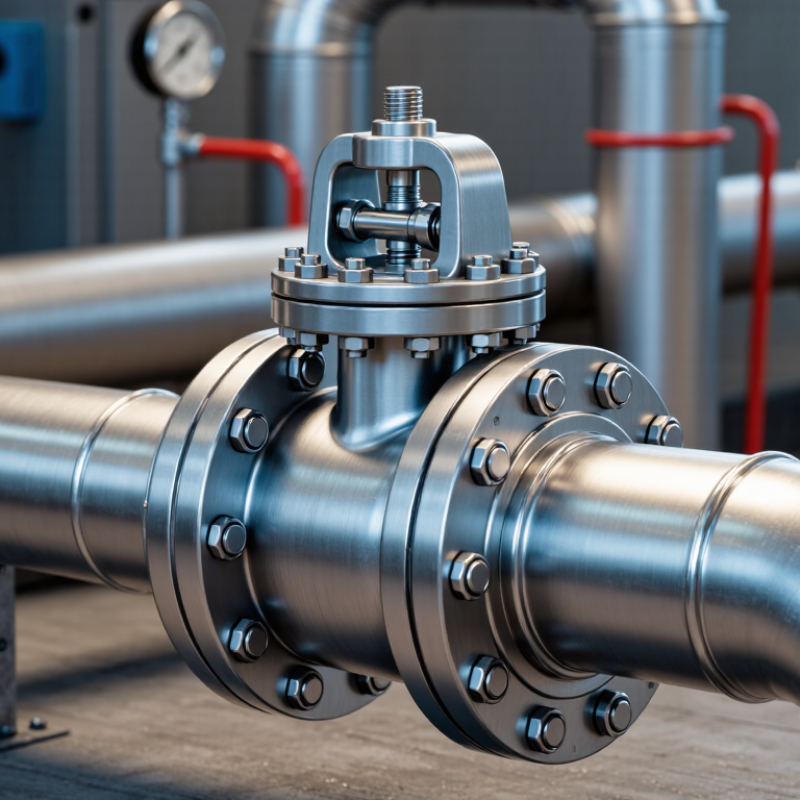
A welded ball valve is a shutoff device with a spherical ball inside its body. The ball contains a drilled passage. When the passage aligns with the pipeline, fluid flows through. A quarter-turn rotates the ball and blocks the passage. This design offers quick operation and low pressure loss.
The valve body is welded directly to the pipe, creating a compact, permanent connection. Proper welding can reduce external leak paths and limit maintenance points. However, installation quality matters greatly. Skilled welders control heat input, alignment, and penetration. After welding, inspectors may use visual checks, pressure testing, or non-destructive examination. The stem transfers handle or actuator movement to the ball. Seats and seals keep the closed valve tight.
When choosing a welded ball valve in 2026, check pressure rating, temperature range, fluid compatibility, and pipe size. Stainless steel may suit corrosive service, while carbon steel can fit many general systems. Do not select by size alone. Consider cleaning access, actuator space, emergency shutdown needs, and future replacement difficulty. Welded connections are not easily removed.
A practical warning remains important. No checklist catches every mistake. A valve rated for the fluid may still fail with poor welding or incorrect sealing materials. Review applicable standards, test records, and operating conditions with a qualified engineer. Small details matter.
How to Choose a Welded Ball Valve in 2026? - What Is a Welded Ball Valve and How Does It Work?
| Selection Dimension | Typical Data or Options | What to Check Before Selection |
|---|---|---|
| Valve Definition | A ball valve with a permanently welded body or welded pipeline connections. | Confirm whether “welded” refers to a fully welded body, butt-weld ends, socket-weld ends, or a combination of these features. |
| How It Works | A spherical ball with a central bore rotates approximately 90 degrees between open and closed positions. | The bore aligns with the pipeline in the open position and turns perpendicular to the flow in the closed position. It is intended primarily for on/off isolation, not routine throttling. |
| Nominal Size | Common sizes range from DN15 to DN1200 and approximately 1/2 in to 48 in, depending on the application. | Match the valve nominal diameter, pipe outside diameter, wall thickness, and required flow capacity. Large sizes may require a gearbox or powered actuator. |
| Bore Design | Full bore, reduced bore, or standard bore. | Choose full bore where low pressure loss, pigging, or minimal flow restriction is important. Reduced bore can lower weight, cost, and actuator torque requirements. |
| Typical Body Material | Carbon steel, stainless steel, low-temperature carbon steel, or alloy steel. | Select material according to fluid compatibility, design temperature, corrosion allowance, impact toughness, and applicable piping material requirements. |
| Ball and Stem Material | Commonly stainless steel or corrosion-resistant alloy with a polished or coated surface. | Check resistance to erosion, corrosion, hydrogen service, sour gas, abrasive particles, and repeated operating cycles. |
| Seat Materials | PTFE-based materials, reinforced polymers, PEEK, nylon, or metal seats. | Soft seats are commonly used for clean fluids and moderate temperatures. Metal seats are considered for high temperature, abrasive, or fire-critical services. |
| Pressure Class | Typical classes include ASME Class 150, 300, 600, 900, 1500, and 2500; metric ratings may also be specified in PN16 to PN420. | Pressure rating depends on material, temperature, size, and design standard. Never select a rating from nominal pressure alone; use the applicable pressure-temperature table. |
| Operating Temperature | Typical service may range from approximately -196°C to 200°C for selected designs; specialized metal-seat valves can cover higher temperatures. | Confirm the actual minimum and maximum design temperatures, start-up conditions, thermal cycling, seat limits, and material toughness requirements. |
| Connection Type | Butt-weld ends, socket-weld ends, flanged ends, or welded body construction. | Match end dimensions, bevel geometry, wall thickness, weld procedure requirements, allowable heat input, and field installation access. |
| Pressure Drop | A full-bore ball valve normally produces low pressure loss when fully open. | Compare the valve flow coefficient, bore size, fluid velocity, viscosity, density, and required flow rate. Avoid using a valve as a permanent throttling device unless specifically designed for it. |
| Leakage Performance | Soft-seated designs can provide very low shutoff leakage; metal-seated designs may have different allowable leakage criteria. | Specify the required seat leakage class, test medium, test pressure, duration, and whether double-block-and-bleed capability is required. |
| Fire-Safe Requirement | Fire-safe construction may include secondary metal sealing and anti-blowout stem features. | For flammable fluids, specify a recognized fire-test requirement and verify that the complete valve design—not only the seat material—has been tested. |
| Stem Configuration | Top-entry or side-entry stem arrangements with anti-blowout construction. | Check stem sealing, external leakage control, anti-static continuity, access for maintenance, and the required operating torque. |
| Actuation | Manual lever, gearbox, pneumatic actuator, electric actuator, or hydraulic actuator. | Size the actuator using maximum breakaway, running, and closing torque, including safety margin, differential pressure, temperature, and emergency operating requirements. |
| Operating Time | Manual operation commonly takes about 90 degrees of rotation; powered operating time varies by actuator and valve size. | Confirm required opening and closing speed, surge-control limits, fail-open or fail-closed action, and compatibility with the control system. |
| Welding Considerations | Permanent welded joints reduce potential bolted-body leakage paths and can provide a compact pipeline assembly. | Use qualified welding procedures, protect seats and seals from excessive heat, verify alignment, perform required non-destructive examination, and pressure-test after installation. |
| Testing and Inspection | Shell test, seat test, low-pressure air or gas test, high-pressure test, visual inspection, and selected non-destructive examinations. | Request material certificates, dimensional records, pressure-test reports, weld inspection records, traceability documents, and actuator test data where applicable. |
| Applicable Standards | Common references include API 6D, ISO 14313, ASME B16.34, ASME B16.10, ASME B16.25, ISO 5208, and fire-safe testing standards where required. | Specify the governing standard edition, design code, inspection level, end-to-end dimensions, pressure class, and project-specific deviations. |
| Suitable Applications | Natural gas, oil, water, district heating, process fluids, cryogenic service, and selected chemical applications. | Evaluate fluid composition, solids content, toxicity, flammability, pressure, temperature, corrosion potential, cleaning method, and maintenance access. |
| Main Advantages | Low leakage potential, compact installation, low flow resistance, strong pipeline integration, and reduced external bolted-joint exposure. | The permanent connection can make replacement more labor-intensive, so verify expected service life, inspection strategy, bypass requirements, and isolation provisions. |
| Recommended Choice for 2026 | Select a fully documented valve with appropriate materials, digital traceability, tested leakage performance, and actuator compatibility. | Base the final choice on the complete duty specification: fluid, size, pressure, temperature, bore, end connection, materials, standards, actuation, testing, installation method, and lifecycle requirements. |