
How to Choose the Right Dual Micro Switch
Choosing a Dual Micro Switch is not just a matter of finding a part that fits inside a housing. The right choice depends on the circuit, the actuator, the available space, and the conditions where the switch will operate. Start by checking the required electrical rating and contact arrangement against the equipment’s specifications. Then consider the operating force, travel, and release point. A switch that feels suitable on a workbench may behave differently once installed behind a tight panel or beside a moving lever.
Small details matter. Compare the manufacturer’s datasheet, not only a product listing. Look for rated voltage and current, mechanical and electrical life, terminal style, mounting dimensions, and any stated temperature or moisture limits. If dust, vibration, or frequent cycling is expected, verify that the switch is specified for those conditions; appearance alone cannot confirm durability. Fit comes first, but ratings cannot be guessed. Check the load type as well, since inductive loads can place different demands on contacts than simple resistive loads.
For prototypes, test the chosen switch in the actual mechanism before finalizing the design. Note whether the actuator is pressed fully, released cleanly, and kept within its specified travel. Measure twice. A close match on paper can still produce awkward alignment, excessive force, or unreliable switching in practice. When two models seem similar, confirm the details with the manufacturer or an authorized supplier. This guide explains the key selection factors and trade-offs, while recognizing that the best option depends on the application—not just the smallest size or lowest price.
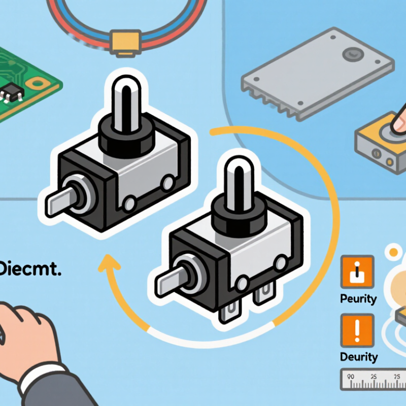
Understanding the Structure and Function of a Dual Micro Switch
A dual micro switch combines two switching mechanisms in one compact housing. Its actuator presses against a spring-loaded internal lever, which moves electrical contacts between open and closed positions. Depending on the design, one actuator may operate two separate circuits together, or the switch may provide two distinct contact sets. The wiring diagram matters. Small parts matter.
Look at the actuator, terminals, mounting points, and housing as a working system. A short plunger may suit a tight space, while a roller lever can respond to movement along a passing surface. Inside, contact arrangement determines whether a circuit opens or closes when pressed. Check the rated voltage and current for the actual load; a motor can demand more at startup than its running current suggests. Listen for the click. It can confirm movement, but not prove reliable electrical contact.
For selection, compare operating force, travel, reset point, terminal style, and expected cycle count. Also consider dust, moisture, vibration, and temperature near the installation. A switch that fits mechanically may still be a poor electrical match. In inspection, gently actuate each section and verify both circuits with a suitable meter, following the manufacturer’s data sheet. Some specifications leave the timing relationship between contacts unclear. That detail deserves a closer check before installation.
How to Choose the Right Dual Micro Switch - Understanding the Structure and Function of a Dual Micro Switch
| Selection Factor | Structure and Function | Common Configurations | How to Choose | What to Verify |
|---|---|---|---|---|
| Dual-switch arrangement | “Dual” can describe two switch units in one assembly or two switching circuits operated by a shared actuator. The exact internal arrangement varies by design. | Two independent mechanisms; or one actuator operating two contact sets. | Choose independent operation when the circuits need separate actuation. Choose a shared actuator when one mechanical event must operate both circuits. | Check the internal diagram, actuator arrangement, and whether the circuits are electrically isolated. |
| Contact form | Contacts change state when the actuator moves past the switch’s operating point. A changeover contact can connect a common terminal to one of two outputs. | SPST (normally open or normally closed) and SPDT (changeover) are common micro-switch contact forms. | Use SPST for a single on/off path; use SPDT when a circuit must switch between two paths or provide complementary outputs. | Confirm terminal identification and the normal state shown in the manufacturer’s wiring diagram. |
| Actuator style | The actuator transfers movement to the internal snap-action mechanism. Its shape affects how the switch meets the moving part. | Pin plunger, hinge lever, roller lever, and simulated roller lever are common styles. | Select a plunger for direct, aligned contact; consider a lever or roller when the mechanism approaches at an angle or slides across the actuator. | Check allowable travel, mounting clearance, approach direction, and actuator wear in the intended application. |
| Operating force and travel | Operating force is the force needed to change contact state. Pretravel, operating position, overtravel, and release position describe actuator movement through the switching cycle. | Values depend on the specific mechanism and actuator; lever versions often have different force and travel characteristics from plunger versions. | Match the switch’s operating force and movement range to the available drive force and mechanical stroke. | Use the product datasheet’s force and travel limits. Avoid exceeding permitted overtravel or applying side loads unless specified. |
| Electrical rating and load | Contact ratings specify the electrical conditions under which the switch is designed to operate. AC and DC ratings can differ, and motor, lamp, or other inrush loads may stress contacts more than resistive loads. | Ratings are model-specific; there is no single current or voltage rating applicable to all dual micro switches. | Choose a model rated for the actual supply, load type, switching frequency, and expected inrush current. | Check the datasheet’s AC/DC and load-category ratings. Use suitable external protection or a relay when required by the application. |
| Terminal and wiring layout | Terminals connect the switch contacts to the external circuit. A dual assembly may provide separate terminals for each contact set. | Solder terminals, quick-connect terminals, or pre-wired leads, depending on the model. | Select a termination style compatible with the wiring method, available space, and required assembly process. | Confirm pin assignment, terminal dimensions, wire size, insulation clearance, and strain relief requirements. |
| Operating life and switching frequency | Mechanical life and electrical life are different specifications. Electrical life depends on the switched load and operating conditions, and is generally not interchangeable with mechanical life. | Manufacturers publish life-test figures under specified conditions; results can differ substantially with load and switching rate. | For frequent switching or a safety-critical function, assess the rated life under conditions close to the real application. | Review test conditions, load type, switching frequency, and applicable safety requirements. |
| Environment and mounting | The housing, mounting features, and any sealing affect installation and resistance to dust or moisture. Protection levels are model-specific. | Panel, bracket, or chassis mounting; sealed and unsealed versions may be available. | Match the mounting dimensions and environmental protection to the equipment location. | Check mounting drawings, temperature limits, ingress-protection details, and any required approvals. |
Note: Electrical ratings, dimensions, force, travel, life, and environmental limits vary by model. Confirm all final selections against the specific product datasheet and the requirements of the complete application.