
What Is an SMPS Power Supply and How Does It Work?
An Smps Power Supply, or switched-mode power supply, converts electrical energy through rapid electronic switching. Unlike a traditional linear supply, it controls power by switching transistors on and off at high frequency. A compact adapter can therefore deliver steady output without wasting as much energy as heat. Inside, components such as a rectifier, switching transistor, transformer, control circuit, and filter capacitors work together. Their arrangement depends on the design and whether the supply steps voltage up or down.
Power-electronics engineer and author Marty Brown has written extensively about power-supply design. A practical paraphrase of the engineering lesson in his work—not a verified verbatim quotation—is: “Efficient switching matters, but reliable performance depends on the entire circuit.” That distinction is important. A transformer may look small, yet poor control or filtering can cause excess ripple, heat, or electrical noise. Not magic. Just coordinated components. This introduction explores what an Smps Power Supply does, how energy moves through its stages, and why feedback helps maintain a stable output when the load changes. For example, a laptop charger must respond as the device draws different amounts of current. Real designs also involve trade-offs among size, efficiency, cost, and noise. There is no single ideal circuit for every use. Understanding those limits makes the technology easier to evaluate—and gives readers a reason to question efficiency claims that lack operating conditions.
What an SMPS Power Supply Is and What It Does
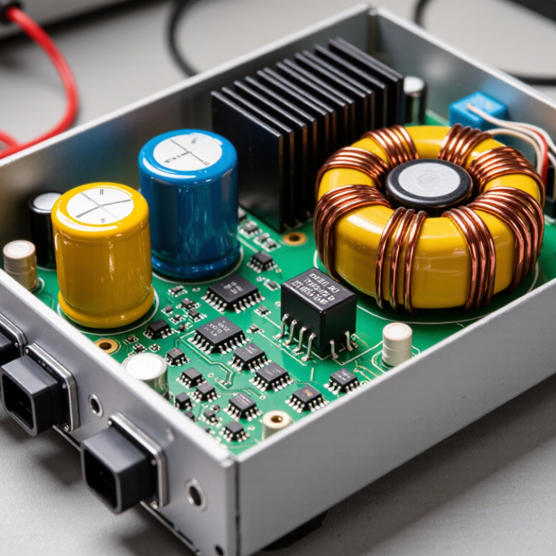
An SMPS, or switched-mode power supply, converts electrical power into a form that a device can use. It may turn household AC into steady, lower-voltage DC for a router, monitor, or control board. Unlike a simple linear supply, it regulates power by rapidly switching electronic components on and off.
Inside, the input is typically rectified and filtered before a switching transistor chops it into high-frequency pulses. A transformer can then change the voltage and provide electrical isolation. On the output side, diodes or other switching components, capacitors, and a control circuit smooth and regulate the power. The result is a more stable output, even when the input or the device’s demand changes. That is the core job.
This compact approach often wastes less energy as heat than a comparable linear supply, though it can introduce electrical noise. Filters and careful circuit design help control that noise. In practical use, check the output voltage, current rating, and polarity against the device’s requirements. A label gives useful clues, but it does not reveal every design trade-off. Even a well-rated supply may behave poorly with an unusual load. That detail is easy to overlook.
What Is an SMPS Power Supply and How Does It Work? — What an SMPS Power Supply Is and What It Does
| Dimension | How It Works | What It Does | Important Detail |
|---|---|---|---|
| Definition | A switched-mode power supply (SMPS) converts electrical power by rapidly switching electronic devices on and off. | It provides the voltage and current needed by electronic equipment. | Unlike a linear supply, an SMPS regulates power through high-frequency switching rather than dissipating excess voltage continuously as heat. |
| Input stage | The supply accepts an input source, commonly AC mains or DC, depending on its design. | It receives power before conversion and regulation. | Input-voltage limits are design-specific and should be checked on the supply’s rating label or technical documentation. |
| Rectification and filtering | In an AC-input design, a rectifier converts AC into pulsating DC. Capacitors and other filtering components smooth the DC. | It creates a DC bus for the switching stage. | The resulting DC is not necessarily safe to touch; power supplies can retain hazardous charge after disconnection. |
| High-frequency switching | Power semiconductor switches, commonly MOSFETs or similar devices, turn on and off rapidly to control energy transfer. | It controls how much energy moves through the supply. | Switching frequency varies by design and operating conditions; it is generally much higher than mains frequency. |
| Energy transfer | A transformer or inductor transfers and stores energy in a controlled way. Some designs provide electrical isolation; others do not. | It can change voltage levels and, in isolated designs, separate the output electrically from the input. | Isolation depends on the circuit topology and construction, not simply on the fact that a supply is switched-mode. |
| Output rectification and filtering | Output diodes or synchronous switches rectify the transferred energy, while capacitors and inductors reduce ripple. | It produces a smoother DC output for the connected load. | Output voltage, current capacity, ripple, and noise depend on the specific design and load conditions. |
| Feedback and regulation | A feedback circuit monitors the output and adjusts switching operation when the output changes. | It helps maintain the specified output as input voltage or load varies within the rated operating range. | Regulation is limited by the supply’s ratings and protection behavior; it does not guarantee the same output under every condition. |
| Efficiency and heat | Switching devices spend less time in intermediate states than a linear regulator, reducing some sources of power loss. | It can deliver power with less heat loss than a comparable linear supply, depending on the design and operating point. | Efficiency is not 100%; switching, magnetic, conduction, and other losses still generate heat. |
| Common applications | SMPS designs are used in equipment such as computers, displays, communications devices, and many battery chargers. | They supply regulated power in a wide range of electronic products. | The required output ratings, isolation, protections, and certifications differ by application. |
In summary: An SMPS converts input power into a regulated output by rectifying, switching, transferring, and filtering energy, while feedback adjusts operation to help keep the output within its specified range.