
What Are the Top Extruder Machine Parts in 2026? The answer depends on the material, output target, and operating conditions. Still, several components shape performance across many extrusion lines: the screw and barrel, feed throat, gearbox, heater bands, screen changer, die, and cooling system. Each has a distinct job. Together, they influence melt consistency, pressure, temperature, and finished-product quality.
Extrusion expert Dr. Chris Rauwendaal’s work points to a useful principle: “The screw is the heart of the extruder.” That idea is practical, not absolute. A screw may be precisely machined, yet poor feeding or uneven barrel heating can still create unstable output. Look closely at the screw’s flight geometry, the barrel’s wear surfaces, and the die’s flow channels. Small defects matter. A worn screw can reduce conveying efficiency; a blocked screen can raise pressure and interrupt production.
This guide examines the key Extruder Machine Parts expected to matter in 2026, including what each component does and what buyers should inspect. It also considers newer monitoring and material choices without treating every upgrade as a guaranteed improvement. Specifications vary by polymer and machine design, so confirm recommendations with the equipment manufacturer and a qualified process engineer. There is no universal parts list. Sometimes, the overlooked seal or thermocouple deserves more attention than a costly new assembly.
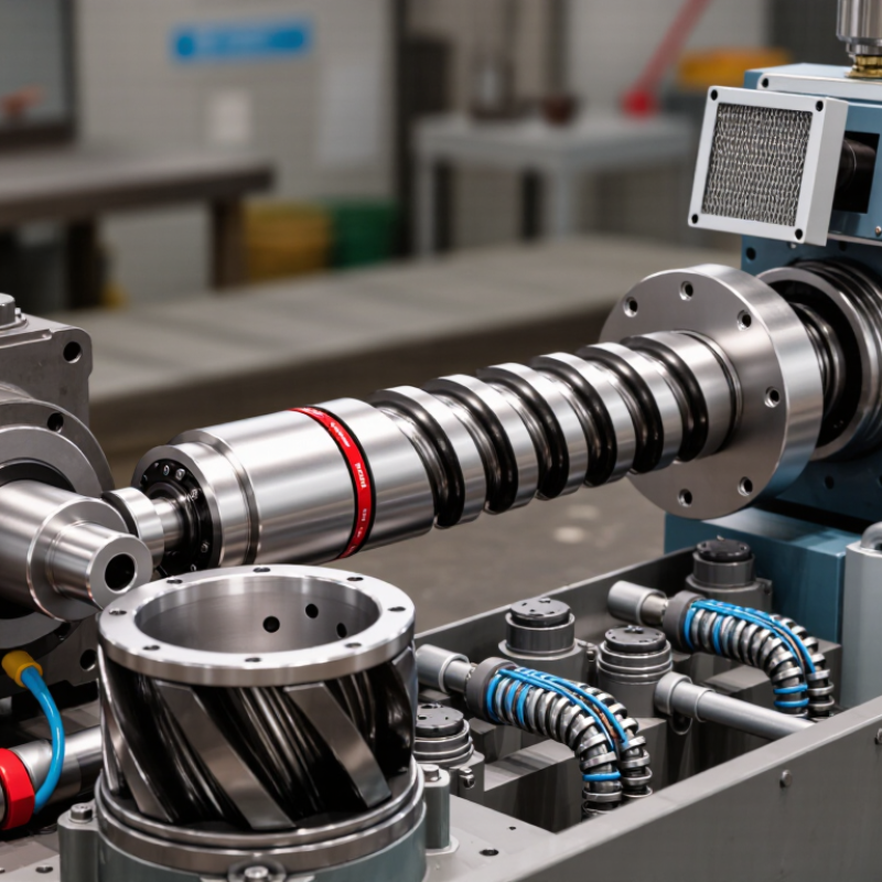
What Are the Top Extruder Machine Parts in 2026?
Core Extruder Components and Their Roles in 2026
A reliable extrusion line depends on several parts working together under steady heat and pressure. The hopper guides pellets into the feed throat, where cooling helps prevent material from softening too early. Inside the barrel, a rotating screw conveys, compresses, and melts the material. Its flights mix the melt, but worn or poorly matched screw geometry can cause uneven output. Small changes matter.
Heater bands and temperature sensors control heat along the barrel, while a gearbox and motor provide the screw’s rotation. A thrust bearing absorbs axial force and helps protect the drive system. Near the outlet, a screen pack catches contaminants and can improve melt consistency, though a clogged pack raises pressure. The die shapes the material into its final profile. It needs careful alignment. In practice, operators should watch melt temperature, motor load, and pressure together; one reading alone can give a misleading picture. Even a well-maintained machine may show variations when feedstock or production conditions change. That judgment can be imperfect. Regular inspections and recorded settings help teams spot changes before they become costly defects.
In 2026, an extruder’s feed system remains a practical starting point for stable production. The hopper should hold enough material for steady operation without encouraging separation or stagnant pockets. Pellets that vary in size may flow unevenly, especially when the hopper walls are shallow or rough. Bridging can stop the feed while the machine still appears to be running normally. That detail is easy to miss.
The throat connects the hopper to the heated barrel, so its temperature and geometry matter. Heat creeping upward can soften pellets too early and create a sticky blockage. Operators can check for this by tracking throat temperature and inspecting the feed opening during planned stops. Conveyance equipment, such as a screw feeder or vacuum loader, must deliver material at a rate the extruder can actually process. Too much feed can raise motor load; too little can cause output to fluctuate. Small changes show up quickly. Keep the material path clean, and verify that hoses have no sharp bends or trapped pellets. A neat installation helps, but it does not guarantee consistent feeding. Real materials behave differently, so settings often need careful adjustment.
| Feed-System Part | Primary Function | Key Design and Operating Facts | Practical Inspection Point |
|---|---|---|---|
| Feed Hopper | Stores pellets, granules, or regrind above the extruder feed opening. | Steep, smooth internal surfaces can help material flow. Hopper capacity should match the material supply rate and production schedule. | Check for bridging, material buildup, contamination, and secure mounting. |
| Hopper Outlet and Feed Throat | Directs material from the hopper into the screw’s feed section. | The opening must suit the machine and screw design. Consistent, unobstructed flow helps avoid interruptions in screw feeding. | Look for blockages, worn surfaces, and trapped or compacted material. |
| Feed-Throat Cooling | Controls heat transfer near the feed opening so material does not soften prematurely. | Cooling may use a water jacket or another designed cooling circuit. Required conditions depend on the resin, screw, and process. | Check coolant flow, leaks, and signs of heat-related material sticking in the throat. |
| Vacuum Loader | Transfers pellets from a bulk container or storage point to the hopper. | Conveys material through a pickup line using vacuum. Loader capacity and line layout should be matched to material demand and conveying distance. | Inspect filters, seals, hoses, and pickup points; confirm that the loader cycles and refills as intended. |
| Pneumatic Conveying Line | Moves material between storage, drying, blending, and machine-side equipment. | Line bends, length, airflow, and material properties affect conveying performance. Excessive conveying can contribute to pellet wear or fines. | Check for leaks, worn bends, blocked lines, and unexpected fines in the material. |
| Hopper Dryer | Removes moisture from moisture-sensitive resin before processing. | Many systems use heated, dehumidified air. Drying temperature and time must follow the resin supplier’s recommendations. | Verify airflow and temperature, keep the hopper covered, and confirm that material is not exposed to ambient air for extended periods. |
| Metering Feeder | Regulates the rate at which material enters the extruder. | Volumetric feeders control delivery by volume; gravimetric feeders use measured weight to adjust the feed rate. Selection depends on process accuracy requirements. | Check calibration, material flow, and consistency between the feeder setting and actual production rate. |
| Blender or Additive Feeder | Combines base resin with colorants, additives, or regrind at a controlled proportion. | Consistent mixing and metering help maintain a uniform formulation. Feed behavior can vary with particle size, shape, and bulk density. | Inspect for segregation, residue, blocked outlets, and changes in the blend ratio. |
The screw and barrel form the main plasticizing assembly in an extruder. The screw moves pellets forward, melts them through heat and shear, then builds pressure for the die. That is the plasticizing core. Plastics Europe’s Plastics—The Fast Facts 2024 report estimates global plastics production reached 413.8 million tonnes in 2023. This figure gives useful industry context, not proof that every line needs a higher-output screw.
A typical screw has feed, compression, and metering sections. In the feed zone, pellets travel along the flights; in compression, the channel becomes shallower and helps form a uniform melt. The metering zone stabilizes flow before the die. Barrel heaters support temperature control, but the screw also generates heat through friction. Too much shear can degrade heat-sensitive material. Too little may leave unmelted particles. The balance depends on resin, output, and operating conditions.
Clearance matters. As the screw and barrel wear, output and melt consistency can suffer, even when the machine still runs. Check dimensions against equipment specifications, and inspect for scoring or uneven wear during maintenance. A polished barrel is not automatically a healthy one. It is tempting to blame every flow problem on the screw; that assumption deserves a second look. Feed quality, temperature readings, and die condition can also explain unstable output.
What Are the Top Extruder Machine Parts in 2026?
Heating, Cooling, and Drive Systems for Process Control
Reliable extrusion depends on more than a target temperature. Barrel heaters bring material to processing temperature, while thermocouples help operators track each zone. A reading that drifts from the setpoint may signal a loose sensor, uneven material flow, or a failing heater. Cooling fans or water channels remove excess heat when the melt runs too hot. Small adjustments matter: a few degrees can change surface finish and dimensional consistency.
The drive system controls screw speed and torque. Its motor, gearbox, and variable-frequency drive work together to move material steadily through the barrel. Watch for rising motor load, unusual vibration, or a changing sound near the gearbox. These signs do not prove a fault, but they deserve a closer inspection. In practice, temperature and screw speed interact, so changing one setting may affect the other. That relationship is easy to underestimate.
Tips: Check sensor readings against a trusted handheld probe during routine maintenance. Keep cooling passages clear, and record heater output, screw speed, and motor load together. Trends often reveal a problem before the product does. One caveat: stable readings do not guarantee uniform melt, especially when feedstock or throughput changes.
In a 2026 extrusion line, the die, screen pack, and sensors do more than complete a machine. They shape the product and reveal process drift while it is still manageable. A die sets the melt’s final profile; small changes in land length, lip gap, or temperature can cause visible thickness variation. Details matter. Operators should inspect deposits and wear during planned stops, then compare measurements with product specifications rather than relying on appearance alone.
Screens filter contaminants and help stabilize flow, but pressure drop tells only part of the story. A rising differential pressure may indicate a loaded pack; an abrupt change can also point to a leak, poor seating, or a feed interruption. Record melt pressure before and after the screen, along with replacement time and output conditions. This makes comparisons useful across shifts. Screen changes should follow validated limits, not a universal schedule, because resin, throughput, and mesh size all affect service life.
Sensors turn these observations into timely decisions. Melt-pressure transducers, temperature probes, and thickness gauges can flag a drifting die or unstable feed. Their readings are trustworthy only when installation is correct and checks use calibrated references. Even then, a sensor cannot explain every defect. A real-world weakness remains: operators may treat a clean dashboard as proof of a good part. Verify with samples, dimensional checks, and documented alarms. Small checks catch costly drift.
Representative processing ranges for common polymers; actual settings vary by grade, equipment, and formulation.
Bar length shows the approximate temperature window in °C. Sensors help monitor process temperatures, while screens filter contaminants and the die shapes the melt. Always follow the material supplier’s processing guidance.
Copyright © 2025 · All Rights Reserved · Franchino Mold & Engineering