Why Choose the Right Milling Cutters?
Why Choose the Right Milling Cutters?
Choosing the right Milling Cutters is not a minor purchasing decision. It directly affects cutting speed, surface finish, tool life, machine load, and production cost. A cutter that looks suitable in a catalogue may perform poorly on a rigid machine, a thin workpiece, or a difficult alloy. The details matter.
Manufacturing expert Serope Kalpakjian describes manufacturing as “the process of converting raw materials into useful products.” Milling Cutters make that conversion practical. Their diameter, flute count, helix angle, coating, and substrate must match the material and machining strategy. Aluminum often needs sharp, polished flutes for chip evacuation. Hardened steel may demand tougher carbide and controlled cutting parameters. Poor selection leaves visible evidence: blue chips, vibration marks, chipped corners, or an overheated spindle.
The right cutter also supports safer, more consistent work. It reduces unexpected changes during production. It can protect dimensional accuracy when tolerances become tight. Still, tool selection is not perfectly predictable. A recommendation based only on material can fail because coolant delivery, workholding, machine power, and operator technique also influence results. That is an uncomfortable detail.
Good engineers verify performance through measured trials. They check spindle load, chip shape, cutting noise, edge wear, and finished dimensions. A small test cut can reveal more than a confident catalogue claim. The best Milling Cutters are not always the most expensive. They are the ones that suit the complete machining system, including its limitations.
What Are Milling Cutters and What Roles Do They Serve?
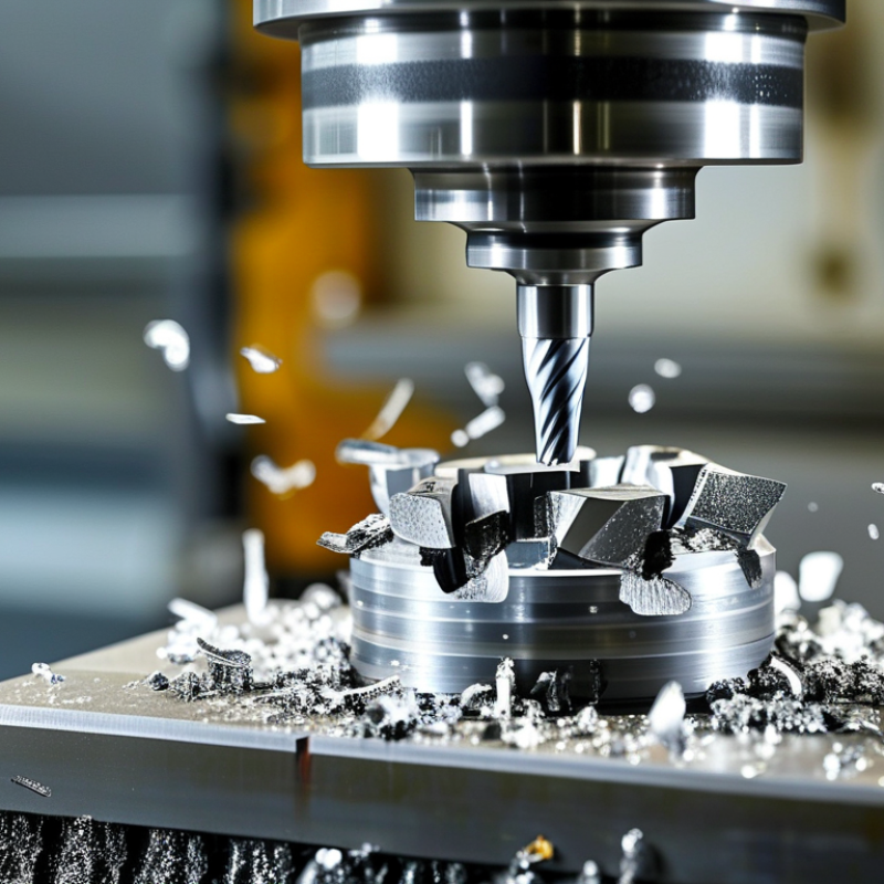
Milling cutters are rotary tools with sharp teeth that remove material from a workpiece. They rotate against metal, plastic, wood, or composite materials. Unlike a single-point tool, a milling cutter uses several cutting edges. Each tooth removes a small chip during rotation.
Common types include end mills, face mills, slab cutters, and ball-nose cutters. Each design serves a different machining role. An end mill can cut slots, pockets, and vertical walls. A face mill quickly levels broad surfaces. A ball-nose cutter follows curved details and produces smoother three-dimensional profiles. Their roles may overlap, but their results do not always match.
In a workshop, the right cutter depends on the material, machine, and operation. Diameter affects cutting force and surface coverage. Tooth count changes chip space and feed potential. Fewer teeth help clear chips in softer materials. More teeth may improve finish on stable machines. Cutter material also matters. Carbide handles demanding cutting conditions, but it can fail under vibration.
I have seen a capable cutter produce poor work because the fixture was weak. The tool was not the real problem. The setup was.
Reliable selection starts with checking the workpiece and required finish. Then match cutter geometry, diameter, and cutting data to the machine’s limits. Keep chips moving away from the cut. Inspect the edge after several passes. A shiny flank may indicate rubbing. A rough wall may suggest deflection or a worn tooth. No selection chart is perfect. Actual results still require observation, adjustment, and a little humility.
How Do Cutter Designs Affect Machining Performance?
Why Choose the Right Milling Cutters?
How Do Cutter Designs Affect Machining Performance?
Cutter design directly shapes cutting forces, heat, chip flow, and surface quality. A high-helix cutter often removes chips smoothly from aluminum. It can also pull the workpiece upward if clamping is weak. A lower helix may provide better control in harder materials, but chip evacuation can suffer.
Flute count changes the balance between productivity and chip space. More flutes can increase feed rates when the machine has enough power. However, crowded flutes may trap chips in a deep pocket. That choice matters. In a shop trial, reducing the flute count improved chip removal and prevented a rough, scratched wall.
Rake angle and edge preparation affect how the tool enters the material. A sharper edge can reduce cutting resistance, yet it may break under interrupted cuts. A small chamfer strengthens the edge, although it can increase heat and spindle load. Tool diameter also matters because larger cutters usually deflect less, but they may not reach narrow features.
Machining results depend on the whole setup, not the cutter alone. Spindle rigidity, workholding, coolant direction, and tool overhang can change the outcome. I have seen a suitable cutter perform poorly with excessive stick-out. Sometimes the design was not the real problem. The setup was. Testing one variable at a time gives more reliable evidence than changing everything at once.
Which Milling Cutter Materials Suit Different Workpieces?
Choosing the right milling cutter begins with the workpiece, not the machine label. High-speed steel suits mild steel, brass, and interrupted cuts at modest speeds. It is tough and forgiving, although it loses hardness when heat builds. Cobalt-alloy HSS adds heat resistance for stainless steel and harder steels. Use steady coolant and avoid rubbing. A dull edge can appear suddenly.
Carbide cutters fit production work and hard steels because they keep an edge at higher cutting speeds. They need rigid fixturing, however. Small vibrations can chip the cutting edge. For aluminum, polished carbide with sharp geometry helps prevent built-up material around the flutes. For cast iron, carbide handles abrasive dust better than ordinary HSS. Ceramic tools can machine some hardened alloys at high speed, but they tolerate shock poorly. Diamond-coated tools work well on abrasive composites and nonferrous materials, not typical steel. That distinction matters.
Tool material alone does not decide performance. Workpiece hardness, alloy, wall thickness, spindle power, and coolant also affect the result. Test a conservative speed, inspect the chips, and check the edge after a short pass. Published cutting data is useful, but real setups vary. A theoretically perfect cutter can fail because the vise is not rigid enough. Setup matters.
How Should You Match Cutters to Milling Operations?
Matching a cutter to the operation starts with the material removal goal. For roughing, choose a strong cutter with a larger core and fewer fragile edges. It should tolerate interrupted cuts and remove stock quickly. For finishing, use more teeth and a smaller radial engagement. This can improve surface quality, but it may increase heat if chip space is insufficient. Slotting needs open flute geometry. Thin walls require lower cutting forces. Hard alloys often need tougher substrates and conservative feeds.
According to the 2024 U.S. Cutting Tool Institute and Association for Manufacturing Technology market report, annual cutting-tool consumption in the United States approached 2.4 billion dollars. That scale shows why small selection errors become costly. ISO 8688-1 and ISO 8688-2 also define tool-life testing methods for milling cutters, including flank wear and failure criteria.
Use those principles on the shop floor: record tool life, spindle load, burr formation, and surface roughness. Geometry matters. A cutter that works well in steel may perform poorly in aluminum. I have seen operators blame feed rates when the real problem was chip evacuation. That mistake is easy to repeat.
Start with the cutter maker’s recommended range, then adjust one variable at a time. Check the chips after the first pass. They should leave the pocket cleanly, not weld against the flute. Perfect matching is uncommon, but measured adjustments make the process more reliable.
What Factors Determine Cutter Life, Accuracy, and Cost?
Choosing a milling cutter is not only a tooling decision. It directly affects cutter life, dimensional accuracy, and machining cost. In daily shop work, I have seen a small mismatch create a large bill. A cutter must suit the workpiece, machine rigidity, spindle speed, and coolant method. Hard alloys may need a tougher cutting edge. Softer materials often need sharper geometry and better chip evacuation. Material alone is not enough.
Cutter life depends heavily on heat, impact, and chip load. Excessive speed can burn the edge, while an aggressive feed can chip it. Stable fixturing matters too. Vibration leaves visible lines on a side wall and shortens tool life. Runout is another quiet problem. Even a small offset makes one flute work harder than the others. Check runout before blaming the cutter. A clean holder, correct projection, and steady coolant can improve consistency. I learned this through repeated adjustments, not perfect calculations.
Accuracy also depends on cutter deflection and wear compensation. A worn tool may still cut, but its diameter gradually changes. Measure critical features during production, especially after long passes. Keep it measurable. Cost should include inserts, setup time, scrap, rework, and machine hours. The cheapest cutter can become expensive after one failed batch. Yet the most expensive option is not automatically better. Test controlled cutting conditions, record results, and question assumptions. Some recommendations look convincing until the chips and measurements disagree.
Why Choose the Right Milling Cutters?
What Factors Determine Cutter Life, Accuracy, and Cost?
The chart compares the typical influence of major cutter-selection factors on tool life, machining accuracy, and total cutting cost. Scores use a normalized 1–10 engineering scale based on common milling practice: higher values indicate a stronger influence. Actual results vary with workpiece material, cutting speed, feed rate, radial engagement, coolant, machine rigidity, and setup quality.
