Why Choose Transformer Switch Gear for Your Project?
Choosing Transformer Switch Gear is a practical decision that affects safety, maintenance, and the dependable operation of a power system. Properly selected equipment can help isolate faults and protect connected circuits, depending on the system design. It also gives technicians a clear, controlled way to inspect or service equipment. Details matter. A dusty indoor room, a humid coastal site, and an outdoor substation can place very different demands on enclosures and insulation. Even cable access can influence installation time. Small choices add up.
A sound selection begins with the project’s voltage, current, fault-level, load, and operating requirements. Engineers should also check the transformer arrangement, available space, environmental conditions, and future expansion plans. Compare equipment ratings and protection features against the project specification, then confirm compatibility with the wider electrical system. Ask how routine inspection will work. That question is sometimes missed. A compact design may save floor space, but it can make access harder; a higher rating may offer flexibility, yet add cost without real value. There is no universal best option. Review manufacturer documentation, applicable technical requirements, and site conditions with qualified electrical professionals before choosing. Careful evaluation helps make Transformer Switch Gear a fit for the project, not just a line item on a purchase list.
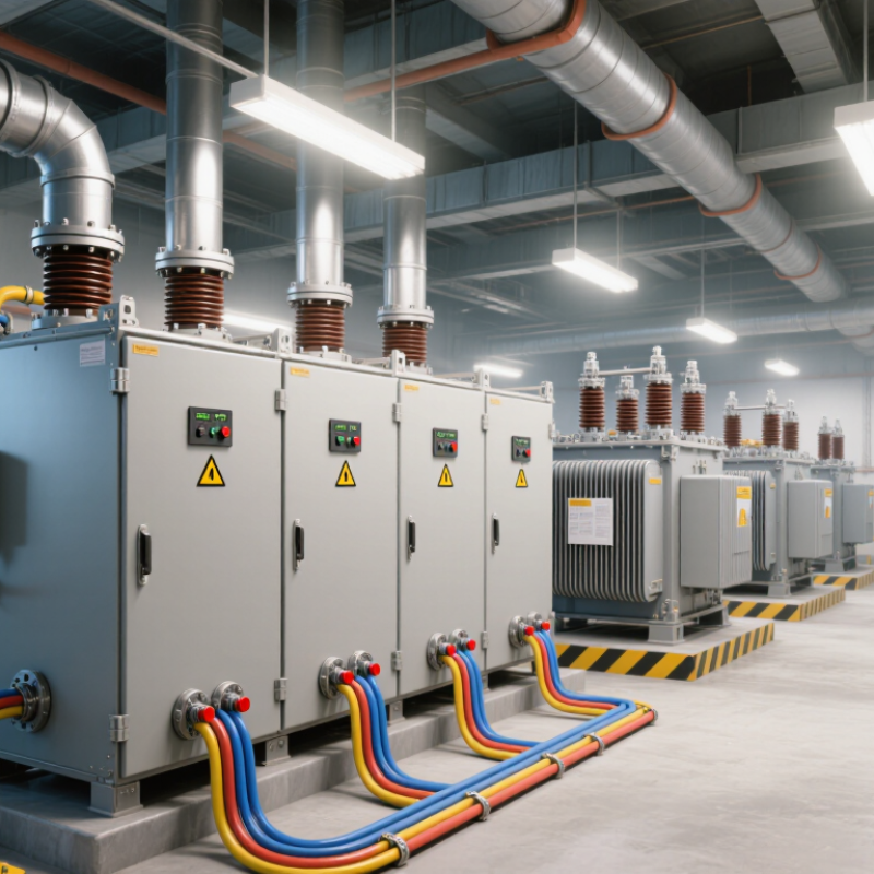
What Transformer Switchgear Is and How It Works
Transformer switchgear is the equipment that connects a transformer to the electrical system and helps control and protect that connection. Depending on the installation, it may include circuit breakers, disconnectors, fuses, protective relays, and grounding switches. The transformer changes voltage; the switchgear manages when power flows and how the circuit responds to abnormal conditions.
During normal operation, current passes through closed switching devices into or out of the transformer. Protective relays monitor measurements such as current and voltage. If they detect a fault, they can signal a circuit breaker to open and isolate the affected section. That matters. A disconnector can provide a visible break for maintenance, but it is not generally intended to interrupt heavy fault current. Grounding switches help make isolated equipment safer to work on when used according to the site’s procedures.
The exact arrangement depends on voltage, load, fault levels, and the required maintenance approach. For example, an outdoor substation may use air-insulated equipment, while a compact indoor installation may use gas-insulated switchgear. In practice, the layout is not always as tidy as a single-line diagram suggests; cable routes, access, and coordination between protection devices also shape the design. Proper ratings and relay settings must be checked for the actual system, not chosen from appearance alone.
How It Connects Transformers to Electrical Networks
Why Choose Transformer Switch Gear for Your Project?
Transformer switchgear forms the controlled interface between a transformer and the electrical network. It does not change voltage; the transformer does that. Instead, circuit breakers connect or disconnect the transformer, while protection relays detect faults and trigger isolation. Disconnectors provide a visible break for maintenance, and busbars route power through the substation. Small details matter: a relay setting must coordinate with upstream and downstream protection, or a fault may interrupt more customers than necessary.
Project selection starts with rated voltage, continuous current, and short-circuit withstand capability. Engineers also check grounding, insulation levels, cable entry, operating access, and how the equipment will be tested. The International Energy Agency’s 2023 report, Electricity Grids and Secure Energy Transitions, estimates that 80 million kilometres of grids must be added or refurbished by 2040 to meet national climate targets. That scale makes reliable grid connections essential. Still, a specification can look perfect on paper. A cramped cable bend or inaccessible test point may complicate installation and maintenance. Walk the site before finalizing the layout, and verify protection settings through commissioning tests. The overlooked details are often the ones that slow a project.
Why Choose Transformer Switchgear for Your Project?
Switchgear connects transformers to electrical networks and provides protection and isolation at the connection point. Selecting equipment for the correct voltage level is essential for a safe, reliable installation.
Typical nominal AC network voltage levels shown for context: 400 V, 11 kV, 33 kV, and 132 kV. Actual voltage levels and switchgear specifications depend on local utility standards and project design.
Key Features That Support Safe and Reliable Operation
Why Choose Transformer Switch Gear for Your Project?
Safe operation depends on more than a strong enclosure. Transformer switchgear combines switching, isolation, and protective devices in a coordinated assembly. When a fault occurs, correctly selected relays can signal a breaker to disconnect the affected circuit. The response must match the transformer’s ratings and the project’s fault levels. Details matter.
Physical safety features help during routine work, too. Mechanical and electrical interlocks can prevent certain unsafe switching sequences. Clearly marked controls and accessible grounding points make procedures easier to follow. A well-designed enclosure also limits access to energized parts and helps protect equipment from dust or moisture. Conditions vary.
Reliability comes from both design and upkeep. Temperature indicators, inspection windows, and sensible cable access can help technicians spot loose connections or unusual heating. That is useful on a busy site, where small signs are easy to miss. Still, no feature removes the need for regular inspection. A relay setting that looks suitable on paper may need adjustment after a system study. Project teams should verify ratings, installation clearances, and maintenance access before selection. Even good equipment can be awkward to service.
Benefits of Using Transformer Switchgear in a Project
Why Choose Transformer Switch Gear for Your Project?
Transformer switchgear helps control, isolate, and protect the electrical connection between a transformer and the wider system. During a fault, correctly selected protective devices can limit equipment damage and help reduce risks to nearby workers. It also gives technicians a defined point for safe isolation during inspections. That matters in a compact plant room, where access can be awkward. Good coordination is essential.
Tips: Check the system voltage, rated current, and expected fault level before selecting equipment. Confirm clearances, cable access, and maintenance space on the actual site drawings. Small details matter.
The right arrangement can make a project easier to operate and maintain over time. It may also reduce installation complexity when switchgear and transformer requirements are planned together. Still, switchgear is not a cure for poor system design. Protection settings must match the transformer and connected loads, and qualified professionals should verify the design. One detail teams sometimes miss is future access: a panel that fits today may be difficult to service after nearby equipment is installed. A site review helps catch that early. Even then, layouts can change, so leave room for practical adjustments.
Factors to Consider When Selecting Transformer Switchgear
Selecting transformer switchgear starts with the electrical duty, not the catalog. Confirm system voltage, continuous current, fault level, and the transformer’s impedance before comparing equipment. The switchgear must withstand expected short-circuit stresses and coordinate with upstream and downstream protection. A mismatch can cause unnecessary trips or leave equipment exposed. Check the installation environment too: dust, moisture, altitude, temperature, and available indoor space affect insulation and enclosure choices. Fit matters.
Future capacity deserves equal attention. The International Energy Agency’s 2023 report, Electricity Grids and Secure Energy Transitions, estimates that 80 million kilometres of grids must be added or refurbished by 2040. It also says annual grid investment needs to rise above $600 billion by 2030. These figures point to the value of planning for load growth, spare feeder capacity, and practical expansion space. Still, forecasts are rarely perfect; avoid paying for capacity that the project cannot justify.
Maintenance and safety shape the real cost of ownership. Compare inspection intervals, replacement-part availability, arc-flash mitigation, and the time required to isolate a fault. Ask engineers to review protection settings alongside transformer data, rather than treating switchgear as a standalone purchase. Plan for access. A compact lineup may save floor space but make cable work awkward later. Record the assumptions behind the selection, including fault calculations and expected load, so future teams can revisit them when operating conditions change.
