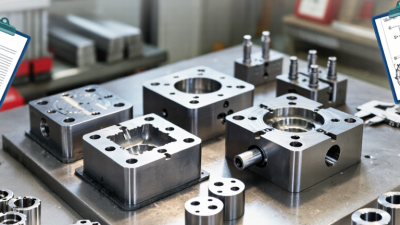
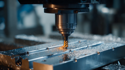
Choosing the right die cast mold begins with the part, not the mold catalog. Define the alloy, dimensions, wall thickness, surface finish, and expected production volume. A thin rib, a deep pocket, or a narrow opening can affect how metal fills the cavity and how the finished part releases. Small details matter. The mold must also suit the casting machine’s shot capacity, clamping force, and tie-bar spacing. A mismatch here can cause delays before production even starts.
Think about cooling, venting, ejection, and maintenance as part of the same decision. Cooling channels influence cycle time and temperature consistency, while vents help gas escape during filling. Ejector pins need careful placement, especially on visible surfaces or delicate features. Ask suppliers how they will address these details, and request drawings or a design review before committing. A sample run can reveal issues that look minor on screen but show up clearly in a real casting. That sounds obvious. It is often missed.
There is rarely one perfect mold design. A low-volume project may favor a simpler, more economical approach, while long production runs can justify greater investment in durability and serviceability. Compare the full operating costs, not only the initial quote. Include expected maintenance, repair access, and the time required to change inserts or clean the mold. Some assumptions will still need testing. That is normal. A careful selection process makes those uncertainties visible early and helps teams choose a die cast mold that fits the part, the machine, and the production plan.
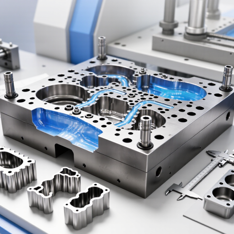
Before selecting a die cast mold, define what the part must do in service. Record the alloy, overall dimensions, critical tolerances, and required surface finish. Be specific about features such as thin ribs, threaded holes, and sealing faces. A sealing face may need tighter control than a hidden outer wall. Small details matter.
Describe the part’s operating conditions, too. Temperature, repeated loads, and contact with other components can affect material and mold design. Share drawings with clear datum points, and flag dimensions that cannot shift during assembly. If the design is still changing, say so. That can prevent premature decisions about slides, cores, or parting lines.
Production goals shape the mold just as strongly as part geometry. Estimate annual volume, expected order sizes, target cycle time, and the available casting machine’s capacity. A high-volume part may justify multiple cavities and more complex mechanisms; a short run may favor a simpler, easier-to-maintain tool. Forecasts are rarely exact. Compare the expected demand with realistic scenarios, including slower ramp-up or design revisions. Also discuss tool life, maintenance access, and acceptable downtime. These trade-offs are not always obvious on a drawing. A practical review with manufacturing and quality teams can reveal where a tight tolerance adds real value—and where it only adds cost.
Choosing a die cast mold starts with the alloy, not the drawing alone. Aluminum needs a cold-chamber process because its higher melting temperature increases thermal loading on the tooling. Zinc’s lower melting point suits hot-chamber casting and can support fine details in small parts. Magnesium is lightweight, but its alloy, machine setup, and handling requirements must be evaluated together. A mold built around the wrong process can cause slow filling, sticking, or uneven cooling.
Scale matters, too. The USGS Mineral Commodity Summaries 2024 estimated global primary aluminum production at about 70 million metric tons in 2023, reflecting the material’s broad industrial use. That figure is not a measure of die-casting demand, but it shows why aluminum alloy selection deserves careful attention. NADCA’s Product Specification Standards for Die Castings also emphasize specifying alloy and part requirements together. Thin ribs, deep pockets, and tight tolerances may call for different gating, venting, and cooling layouts.
A practical check is to review the alloy’s fluidity, shrinkage, corrosion needs, and operating temperature against the part’s geometry. Then ask the foundry how its chosen process handles those features. Small details matter. I would treat the first mold design as a well-informed hypothesis, not a guarantee; real trial data can still expose weak spots.
| Alloy and Typical Applications | Common Casting Process | Mold Material and Construction | Key Mold Design Priorities | Selection Guidance |
|---|---|---|---|---|
| Zinc alloys Small, detailed components such as housings, connectors, and hardware |
Usually hot-chamber die casting; cold-chamber equipment is used for some alloys or applications | Tool steel is commonly used. The mold must suit the alloy, machine, production volume, and required surface finish. | Fine cavity detail, reliable venting, controlled gate design, and durable slides or cores where undercuts are needed | Hot-chamber production can support fast cycles for suitable zinc alloys. Confirm alloy compatibility and machine limits before fixing the mold layout. |
| Aluminum alloys Automotive, appliance, industrial, and electronic components |
Typically cold-chamber die casting | Heat-resistant hot-work tool steel is commonly selected for production tooling. Cooling channels and local thermal management are important. | Resistance to thermal fatigue and erosion, balanced filling, effective venting, robust inserts, and accessible cooling circuits | Choose the mold for the alloy’s filling behavior, casting geometry, and expected production volume. Large or thick sections may need particular attention to filling and solidification. |
| Magnesium alloys Lightweight structural parts, housings, and brackets |
Hot-chamber or cold-chamber die casting, depending on the alloy, machine, and part requirements | Tool steel is selected to withstand operating temperatures and repeated thermal cycling; mold design should be coordinated with the chosen machine and process. | Controlled metal flow, suitable venting, uniform thermal conditions, and safe integration with the casting process | Do not select the mold independently of the machine and process. Confirm alloy-specific handling, machine compatibility, and the foundry’s safety procedures. |
| Copper-based alloys Specialized components requiring properties such as strength or wear resistance |
Generally cold-chamber die casting with specialized equipment and tooling | High-temperature-resistant tooling materials and carefully engineered inserts may be required; tooling choice depends strongly on the specific alloy and process. | Manage high thermal loads, die wear, thermal fatigue, and the demands of filling and ejection | Use a specialist tooling review before committing to a mold design. Confirm that the alloy, machine, and tool materials are suitable for the intended production conditions. |
Practical check: Before approving a mold, align the alloy grade, casting process, machine specifications, part geometry, expected production volume, and quality requirements. Final mold material and layout should be confirmed with the die caster and tooling supplier.
Cavity layout affects more than how many parts a die can produce per cycle. It also influences metal flow, cooling balance, and tool strength. For a multi-cavity die, keep cavities positioned to support similar flow-path lengths from the runner. Uneven filling can leave one cavity short while another experiences excess pressure. Check spacing against cooling channels and the die’s load-bearing areas, not just the available footprint. Small details matter.
The parting line should let the die open cleanly and release the casting without trapping features. Place it where flash can be trimmed accessibly and where any witness line is acceptable on the finished part. A line across a sealing face or prominent surface may create extra finishing work. Draft, ejector-pin locations, and side-core movement also need to fit the chosen line. A tidy drawing can hide a difficult release.
Review the layout with a section view and a basic fill-and-ejection review before committing to tooling. Ask where air may become trapped, where metal fronts meet, and whether pins can push without bending thin walls. These checks reduce avoidable revisions, though they cannot predict every production issue. I would still expect to refine the design after trial shots; real filling behavior sometimes challenges a clean-looking model.
How to Choose the Right Die Cast Mold?
Mold material, cooling, and ejection design shape tool life and casting quality. Select steel suited to the alloy’s temperature, production volume, and expected thermal cycling. Hot-work tool steel is common, but grade selection should reflect heat checking, wear, and repair needs. A harder steel is not automatically better if it becomes difficult to maintain.
Cooling channels should remove heat evenly, not merely quickly. Place them near thick sections and likely hot spots, while keeping enough material around each channel for strength. Uneven cooling can cause shrinkage, distortion, or long cycle times. Small details matter. Ejection pins need enough force to release the casting without marking or bending it. Use suitable draft, and position pins on robust areas that can tolerate contact. Review the part geometry with the mold designer before locking in the layout.
Tips: Ask for cooling and ejection plans, not just a tool quote. Check proposed pin locations against visible surfaces and thin walls. If possible, compare temperature readings and casting defects during trials. A clean simulation can still miss shop-floor variation, so leave room to adjust the process.
A die cast mold should be priced by its cost per acceptable shot, not by its purchase price alone. Ask suppliers to separate mold design, machining, inserts, cooling channels, and trial runs. A lower quote may omit spare cores or detailed maintenance instructions. Those omissions can become expensive later.
Service life varies with alloy, part geometry, die steel, and thermal control. NADCA’s Die Casting Handbook and ASM Handbook, Volume 15, describe these process factors; industry planning references often use roughly 100,000 shots for aluminum dies and up to 1 million for zinc dies. Treat these as estimates, not promises. For example, a 30,000-dollar tool lasting 100,000 shots adds 30 cents per shot before repairs. Check the supplier’s assumptions against your alloy and production cycle.
Maintenance changes the real cost. Inspect vents and parting lines for buildup, check cooling circuits for scale, and record cracks or flash after each production run. Small repairs matter. A missed crack can damage a replaceable insert or force an unplanned shutdown. Ask for a shot-based inspection schedule and the expected cost of common repairs. I would also compare two scenarios: routine maintenance completed on time, and maintenance delayed during a busy production week. That second estimate may feel uncomfortable, but it is often more realistic.
Copyright © 2025 · All Rights Reserved · Franchino Mold & Engineering