
10 Tips for Choosing the Right Plastic Mold Die
Choosing the right plastic mold die is a production decision, not merely a purchasing task. It affects part quality, cycle time, maintenance, material waste, and delivery risk. Grand View Research valued the global injection molded plastics market at approximately USD 387.3 billion in 2022. Its report also projects continued growth through 2030. That scale increases pressure on manufacturers to select tooling carefully.
Small details matter. A polished cavity can improve appearance. A balanced runner system can reduce uneven filling. Proper cooling channels can shorten cycles around every molded part. According to John Bozzelli, an injection-molding consultant and founder of Scientific Molding, “The mold is the heart of the injection molding process.” The quote is simple. The decision is not.
This guide presents ten practical tips for evaluating a plastic mold die. It considers steel selection, cavity design, tolerances, cooling, ejection, maintenance access, supplier experience, and total ownership cost. Reports from MarketsandMarkets identify automotive, packaging, medical, and consumer products as major injection-molding application areas. Each sector creates different tooling demands. Medical components may require stricter validation. Automotive parts may prioritize durability and dimensional stability. Packaging often demands speed.
A checklist helps. It cannot replace engineering judgment. Some designs look economical until a cooling problem appears during production. Others pass initial trials but become expensive after repeated repairs. Reviewing sample parts, mold-flow results, inspection records, and maintenance plans can reveal those weaknesses before approval. The best plastic mold die is not always the cheapest one. It is the one that performs reliably under real production conditions.
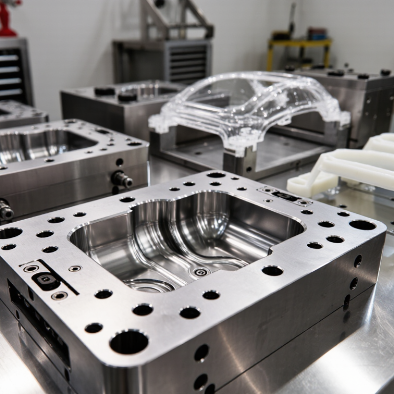
Define the Product Requirements and Mold Performance Goals
10 Tips for Choosing the Right Plastic Mold Die
Define the Product Requirements and Mold Performance Goals
A reliable mold starts with a precise product definition. Record resin type, part weight, dimensions, wall thickness, tolerances, surface finish, and expected annual volume. Include weak points, such as thin ribs, deep corners, or visible weld lines. Write it down.
The OECD’s Global Plastics Outlook reports that global plastic production reached 460 million tonnes in 2019, nearly twice the 2000 level. This growth increases pressure on manufacturers to control waste, energy use, and cycle stability. Therefore, define acceptable scrap rates before selecting the mold structure. For recycled or filled materials, specify moisture limits, abrasive content, and melt-flow variation. Small changes can affect gate wear and filling pressure.
Performance goals must be measurable. Set targets for cycle time, cavity balance, cooling variation, dimensional accuracy, mold life, and maintenance intervals. A mold designed for 100,000 shots should not be priced like one designed for ten million. That sounds obvious. It is often missed.
UNEP’s 2023 Turning off the Tap report identifies redesign, reuse, and improved recycling as major paths toward reducing plastic pollution. These goals influence mold decisions, including part lightweighting, simpler separation, and compatibility with recycled feedstock. Avoid promising perfect performance too early. Resin data may be incomplete, simulations may differ from production, and the first trial may expose assumptions that need revision. Consider a pilot cavity or staged validation before committing to the final die.
| No. | Selection Dimension | Product Requirement to Define | Recommended Performance Target | Mold Design and Tooling Implication | Verification Method |
|---|---|---|---|---|---|
| 1 | Part Function | Identify the loads, movement, sealing, impact, chemical exposure, and operating temperature the molded part will experience. | Document peak mechanical load, service temperature range, expected life, and critical failure modes before tool design begins. | Select a suitable resin family, wall structure, rib layout, draft angle, and gate location based on actual use conditions. | Functional analysis and application test plan |
| 2 | Material Selection | Specify the polymer grade, filler content, shrinkage behavior, moisture sensitivity, and processing temperature. | Use one approved material grade for tool trials whenever possible; record the supplier data-sheet processing window. | Adjust runner sizing, venting, cooling, mold steel, and surface finish to match the material's flow and wear characteristics. | Material data-sheet review and trial molding |
| 3 | Dimensional Accuracy | Separate critical dimensions from reference dimensions and define tolerances according to function. | Set explicit tolerances for mating features, holes, sealing surfaces, and assembly datums instead of applying one tolerance to every feature. | Account for material shrinkage, warpage, mold temperature variation, cavity balance, and post-molding dimensional change. | Coordinate measurement inspection |
| 4 | Surface Finish | Define whether each visible or functional surface requires a polished, textured, matte, or machining finish. | Use measurable surface-finish specifications where practical; for reference, polished surfaces may require a lower roughness value than textured surfaces. | Choose the appropriate polishing, etching, EDM, or machining process and protect cosmetic areas from ejector or weld-line marks. | Surface comparator and roughness measurement |
| 5 | Wall Thickness | Define nominal wall thickness, allowable variation, transitions, ribs, bosses, and other thick sections. | Maintain reasonably uniform walls and use gradual transitions; avoid abrupt thickness changes that can increase sink marks and warpage. | Apply coring, balanced ribs, optimized gate placement, and local cooling to improve filling and solidification uniformity. | CAD review, mold-flow analysis, and section inspection |
| 6 | Production Volume | Estimate annual demand, total lifetime quantity, production speed, and acceptable maintenance downtime. | Classify the tool as prototype, low-volume, medium-volume, or high-volume based on projected shots and required uptime. | Determine cavity count, steel grade, replaceable inserts, cooling layout, automation readiness, and spare-component requirements. | Demand forecast and cycle-time calculation |
| 7 | Cycle Time | Define the target cycle and identify whether cooling, filling, injection, or ejection is the main bottleneck. | Establish a repeatable cycle target that meets output needs without exceeding the material's recommended processing limits. | Optimize cooling-channel distance, channel diameter, conformal cooling where justified, runner design, and ejection sequence. | Timed production trial and temperature monitoring |
| 8 | Ejection and Part Release | Define release direction, undercuts, allowable ejector marks, part stiffness, and any required slides or lifters. | Release the part without deformation, whitening, tearing, sticking, or visible damage at the specified production cycle. | Use adequate draft, balanced ejector placement, suitable venting, and correctly sized slides, lifters, or collapsible mechanisms when needed. | Ejection-force observation and visual inspection |
| 9 | Quality and Process Capability | Identify critical-to-quality characteristics, inspection frequency, traceability needs, and process-control requirements. | Define acceptance criteria for dimensions, appearance, weight, assembly, and function; use capability studies for critical features when required. | Provide stable process windows, cavity identification, sensors where justified, robust venting, and easy access for maintenance and inspection. | First-article inspection and capability study |
| 10 | Maintenance and Service Life | Define expected tool life, cleaning intervals, replacement parts, corrosion exposure, and maintenance skill requirements. | Plan preventive maintenance based on shot count, wear indicators, material abrasiveness, and observed process stability. | Use replaceable wear components, accessible fasteners, proper corrosion protection, standardized components, and documented maintenance points. | Maintenance schedule and shot-count records |
Related Posts
-
Why Choose a Plastic Mold for Global Manufacturing?
-
How to Choose the Right Plastic Mold Supplier?
-
2026 Best Plastic Injection Die for Optimal Production效率?
-

How to Choose the Right Plastic Injection Molding Die?
-
What is a Plastic Injection Molding Die and How Does It Work?
-
How to Choose the Right Plastic Mold for Your Needs?